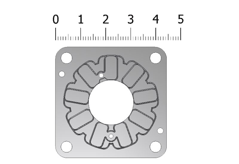
Dimensions
Together with our experienced engineers, we accompany the component design
of our customers from the beginning to exploit the full potential of AM. The focus here is on small to medium-sized components, as the variation in with the size of the component, the variation of the component dimensions also increases. For this reason, MIMplus Technologies has specialised in the production of parts with an with an average weight of between 0.01 and 50 g, although larger components are larger components are also possible. At most, MIMplus currently manufactures components with a weight of ~100 g.
General tolerances
The strongly component and material-dependent tolerances are determined by our experts together with you. By taking AM into account as a manufacturing process at an early stage, an optimum component design can be achieved and tolerances can be minimised. The following geometric guidelines are the most important criteria for a successful production of AM components and should be considered as early as possible in the component design. Targeted implementation enables rework to be reduced or additional calibration steps to be avoided, thus optimising costs.
|
Nominal dimension / mm |
Tolerance / mm |
|
< 3 |
|
|
3 – 6 |
± 0,06 |
|
6 – 15 |
± 0,075 |
|
15 – 30 |
± 0,15 |
|
30 – 60 |
± 0,25 |
|
> 60 |
± 0,5% of the nominal dimension |
The following geometric guidelines are the most important criteria for successful production of MIM components. In the component design, these criteria should be considered at the earliest possible stage. Targeted implementation reduces rework or avoids additional calibration steps - thus optimizing the costs.
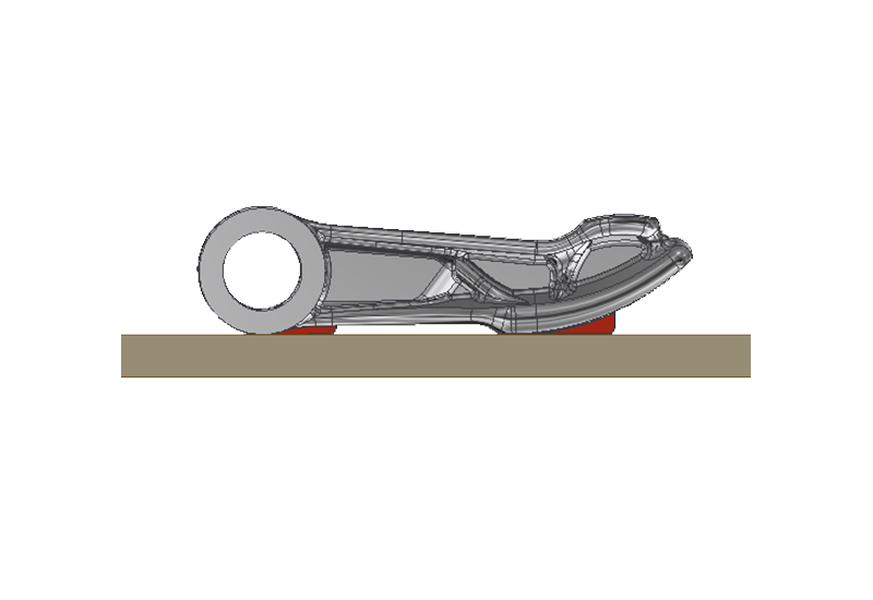 Support surface
Analogous to our MIM components, AM parts must also be placed on a ceramic sintering base. In order to prevent deformation of the components during these production steps, the components should have as flat a contact surface as possible. If this cannot be realised in the component design, our experts have a wealth of experience in the use of clever support variants or very easily removable supports.
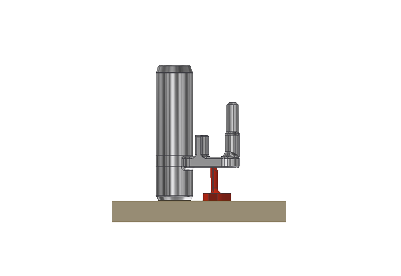
Support structures
In addition to the requirement to prevent or minimize distortion, a stable position of the components is also possible. Components that tend to fall over during transportation can be stabilized by supports. Furthermore, an appropriate choice of material can compensate for the lack of a plane surface.
 Wall thickness distribution
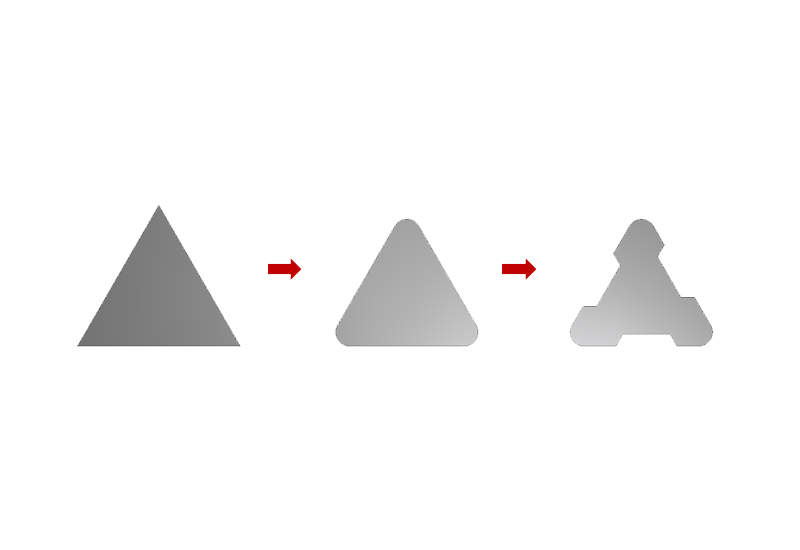
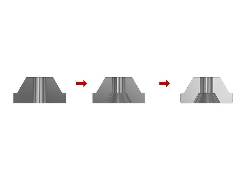
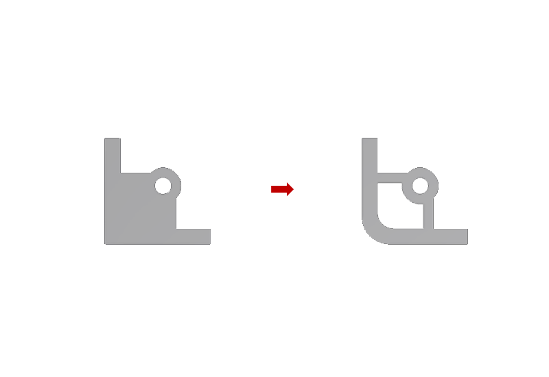
Constant and even wall thicknesses ensure the highest degree of dimensional accuracy and reproducibility. This makes it possible to significantly reduce the weight of the component and save raw materials, which also has a direct impact on component costs. In addition to material savings, the risk of blowholes, sink marks and distortion after sintering can be significantly reduced. The even wall thickness enables the consistent component shrinkage over the entire component and thus helps to master the problems mentioned above. Core removal is also a popular solution to avoid material accumulation.
Material cross-section
The minimum possible wall thickness of a MIM component ranges from 0.3 - 0.5 mm., Material cross sections of > 5 mm should be avoided at most.
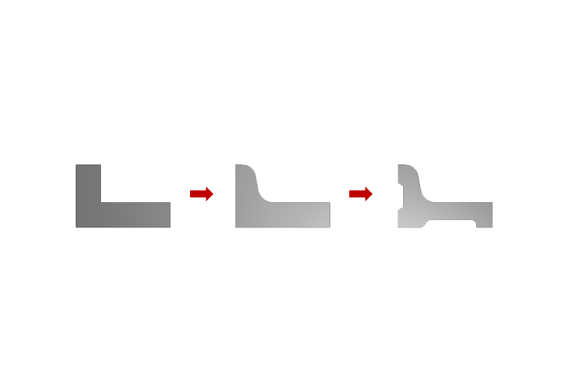
Transitions
In general, rounded edges are preferable to sharply shaped edges. Due to the reduced notch effect, this has a positive effect on the mechanical mechanical properties of the green compact and the sintered part.